T series convectors are our smallest units designed for efficient heating. They are a great choice for use with heat pumps due to efficient heat transfer even at low heating medium temperatures
Quiet operation
T convectors show low noise values in their category. At low and medium speeds, noise does not exceed the common noise background. The microprocessor control unit takes care of the smooth operation of the fan
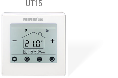
Compatibility with control systems
The control unit also offers a wide range of settings, allowing the optimal convector control by various types of thermostats, BMS or Smart Home systems.
Ecological and economic solution
Due to the low volume of water in the exchanger and the high heat transfer efficiency, are the T convectors valuable for environmentally friendly and energy efficient heating. Low water volume minimizes losses in distribution and reduces the reaction times of the system.
A wide range of accessories
For your comfort, the T series convectors can be ordered with the complete accessories needed for easy installation and a reliable function. An overview of available accessories can be found on the MINIB website.
ORIENTATION AND CONNECTION

When ordering T series convectors, it is necessary to specify the orientation of the convector (left/right) and the water connection (straight/corneous).
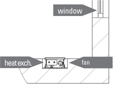
Convector as the main source of heating
If the convector works as the main heat source we recommend to install the convector with the exchanger to the room side.
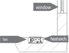
Convector as an additional source of heatling
If the convector is used as an additional heat source, which prevents the condensation of the window, install the convector with the heat exchanger towards the window.
CONNECTION OPENINGS
The convector is supplied with pre-cut holes for all connection directions and all variants of connection accessories. Simply push-out the holes according to the connection direction you have chosen. The positions of the connection openings for the individual dimensions of the convector are shown in the drawings. The openings are placed symmetrically according to the longitudinal and transverse axes of the convector.
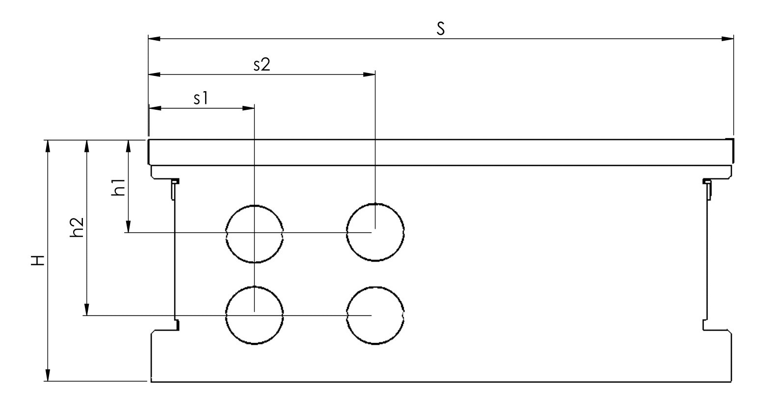
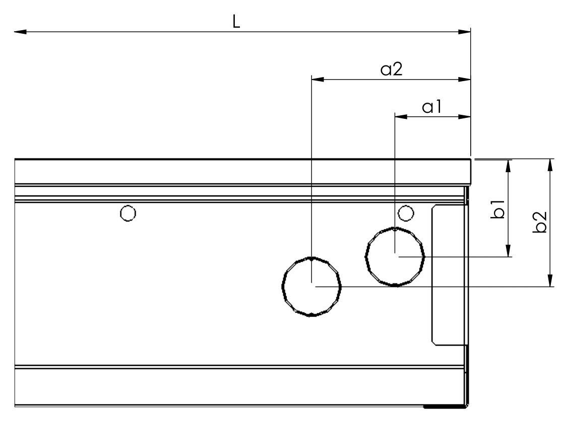
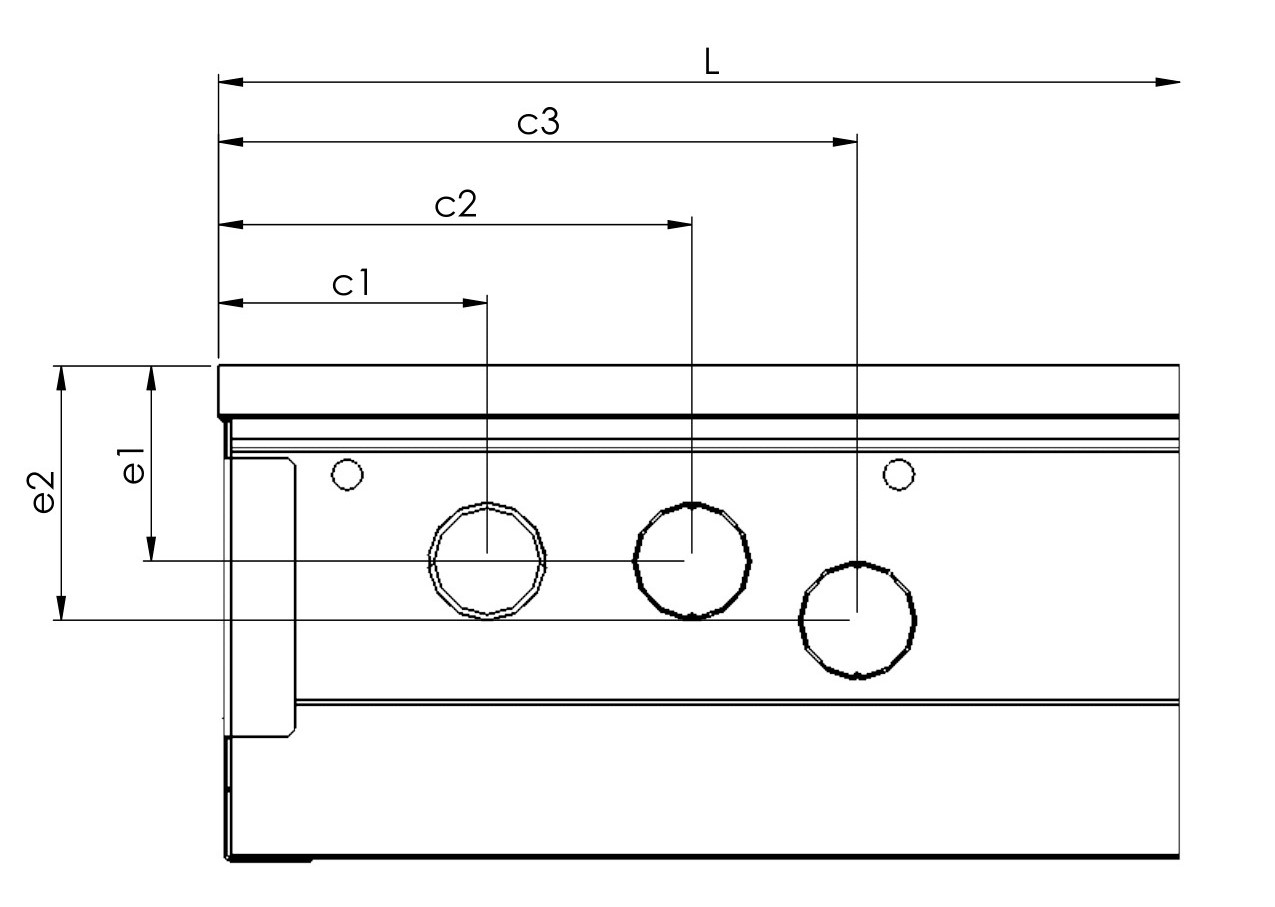
| S | s1 | s2 | H | h1 | h2 | a1 | a2 | a3 | b1 | b2 | c1 | c2 | c3 | e1 | e2 | |
|---|---|---|---|---|---|---|---|---|---|---|---|---|---|---|---|---|
| T 109 X 125 | 109 | 33 | 77 | 125 | 40 | 34 | 34 | 36 | x | 43 | 78 | 34 | 38 | x | 43 | 78 |
| T 165 X 65 | 165 | 52 | 115 | 65 | 46 | x | 38 | 76 | x | 38 | 76 | 38 | 76 | 126 | 45 | X |
| T 165 X 125 | 165 | 50 | 112 | 125 | 55 | x | 38 | 76 | 98 | 54 | 89 | 36 | 76 | 98 | 54 | 89 |
| T 243 X 65 | 243 | 52 | 115 | 65 | 46 | x | 38 | 76 | x | 38 | 76 | 38 | 76 | 126 | 45 | X |
| T 243 X 80 | 243 | 52 | 115 | 80 | 46 | x | 38 | 76 | x | 50 | x | 38 | 76 | 126 | 50 | x |
HEATING POWER
WATER CONNECTION ACCESSORIES
- connection WITHOUT HEAD
- connection WITH ELECTROTHERMAL HEAD
- connection WITH CUSTOMER HEAD (after consultation)
The type of connection accessories varies according to the size and direction of the connection. Connection accessories are packed separately and are not included in the standard convector delivery. The table below shows compatible connection accessory sets. If you require non-standard or custom connection accessories, please ontact your sales representative.
Connection set typically include:
- flex hoses
- ball valve or screw fitting
- thermostatic valve (only sets ready for head)
| WITHOUT head | READY for head | |||||
|---|---|---|---|---|---|---|
| L1/R1 | L2/R2 | L3/R3 | L1/R1 | L2/R2 | L3/R3 | |
| T 109 x 125 | PB²⁾ | PF¹⁾ | PF¹⁾ | PJ3) | - | - |
| T 165 x 65 | PB²⁾ | PF¹⁾ | PF¹⁾ | - | - | - |
| T 165 x 125 | PA¹⁾ | PE¹⁾ | PE¹⁾ | PI3) | PM3) | PM3) |
| T 243 x 65 | PA²⁾ | PE¹⁾ | PE¹⁾ | PI¹⁾ | PM3) | PN3) |
| T 243 x 80 | PA | PE | PE | PI | PM | PN |
GRILLES
The stainless steel grate must be ordered with the convector due to the modification of the convector structure. Transverse grids are supplied as standard, if you are interested in a LONGITUDINAL GRID, please contact your sales representative.
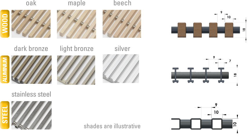
Transverse grids are supplied as standard, if you are interested in a LONGITUDINAL GRID, please contact your sales representative.
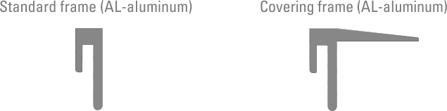
FRAMES
The frame is assembled from an aluminum profile with 45° joints. It comes in the same basic colors as the aluminum grilles. For other convector edge terminations, contact your sales representative.
REGULATION
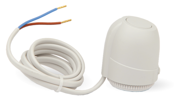
Regulation of the convector with fan is possible through an electrothermal head that controls the flow of water into the convector.

INSTALLATION GUIDE
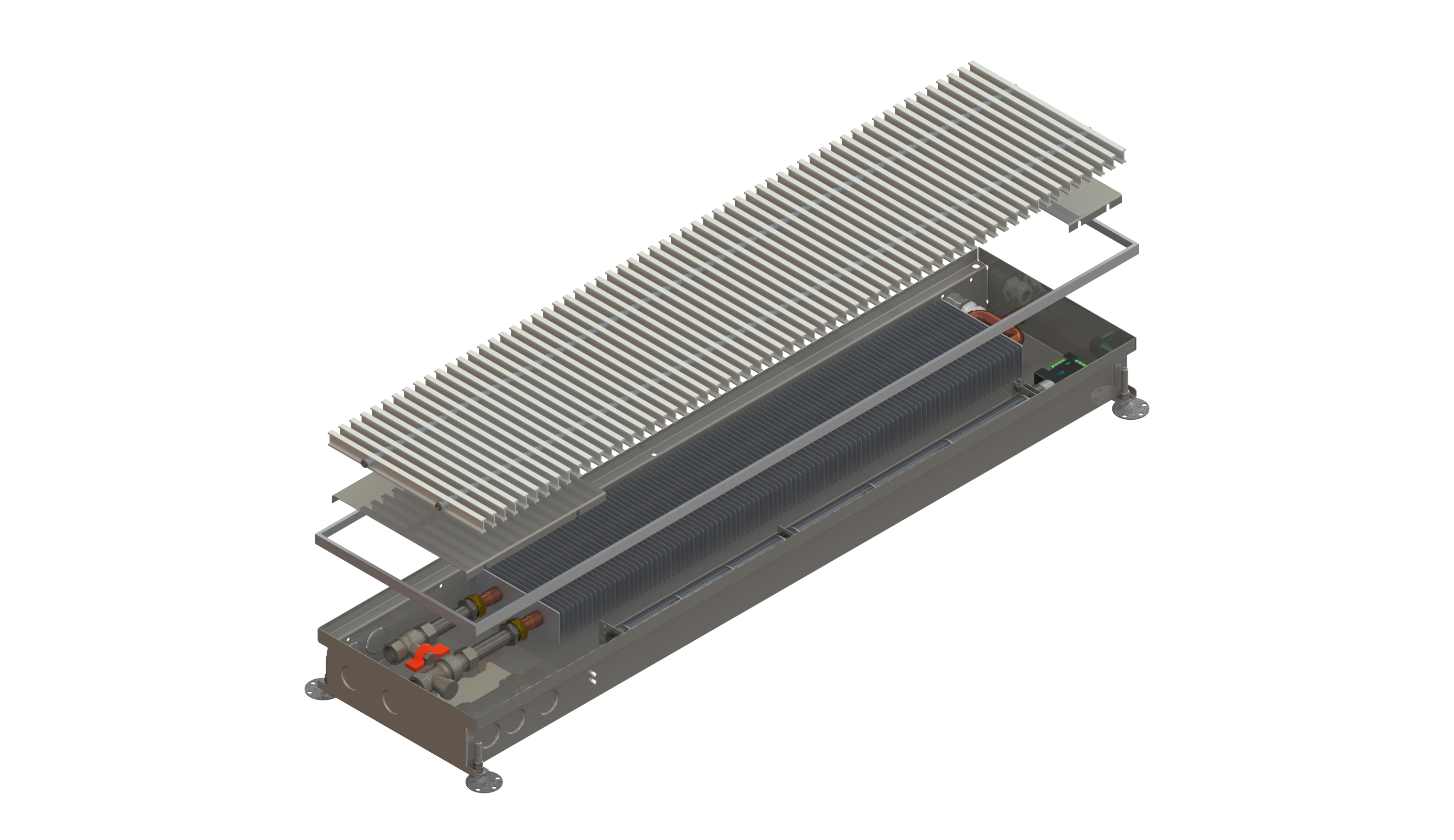
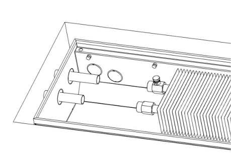
UNIT DESCRIPTION
The standard delivery of the convector includes the convector itself, anchoring accessories and a standard frame. All other accessories (cover grille, connection accessories, control elements, etc.) must be ordered and specified separately when ordering.
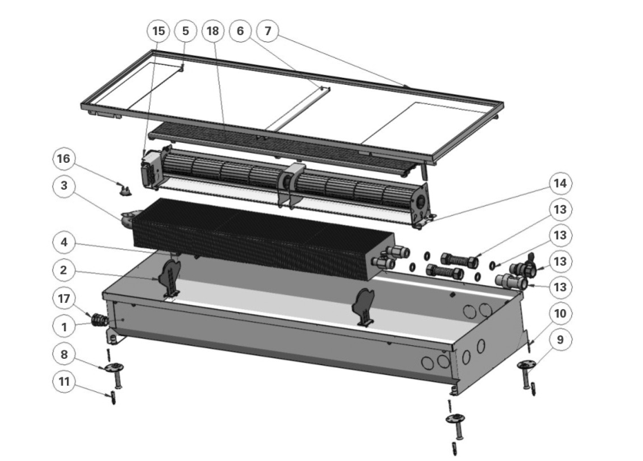
| PIC. 1: Composition of floor convectors - standard construction |
|---|
 |
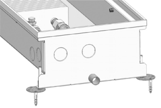
| PIC. 2: Composition of floor convectors – universal construction |
|---|
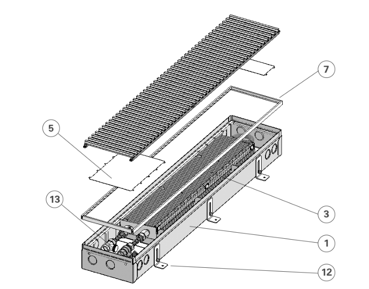 |
- TROUGH – according to the convector type.
- HEAT EXCHANGER HOLDER – supports the heat exchanger body and keeps it in correct vertical position. (Material of the holder depends on the convector type.)
- HEAT EXCHANGER – copper pipes with pressed-on aluminum fins through which the heating water flows.
- RUBBER ANTI-VIBRATION PAD – for vibration attenuation and mounting of cover panel and fan modules.
- COVER PANEL – cover panel covers the unused space. The second cover panel covers the water connection and electronics connections.
- STRUT – all-metal strut maintains the shape of the convector trough during installation.
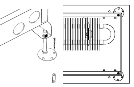
- CONVECTOR FRAME – should be perfectly aligned with final floor. When using a cover molding the upper edge of the molding covers the floor.
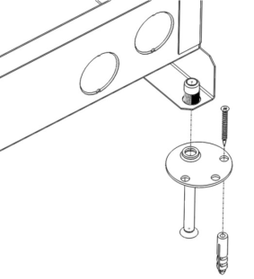
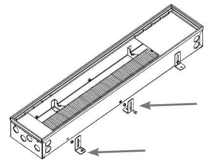
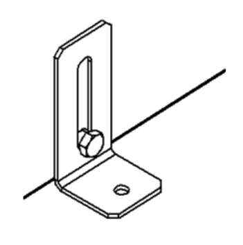
- ANCHORING FOOTING – intended for convector mounting and accurate positioning in unfinished floor.
- ADJUSTING SCREW – intended for fine positioning of convector before pouring of concrete.
- WOOD SCREW – for fixing the footing attachment to the floor.
- SCREW ANCHOR – screw fixing in the concrete floor.
- ANCHOR LEG - (PIC. 2) the number of pieces varies according to the length of the convector
- CONNECTION ACCESSORIES1)
FOR TRENCH HEATERS WITH A FAN: - FAN – used for forced convection
- CONTROL UNIT – fan motor control unit for convectors for dry environment.
- TEMPERATURE SENSOR – heat exchanger temperature sensor.
- CABLE GROMMET – intended for 24 V DC or 12 V DC/AC power supply cable (24V for HCX/HCX4P).
- FILTER2) – to protect the fan modules against larger particles. It also protects the fan against dust. Convector with filters can be provided with a walk-on grille with greater bar sparing.
BEFORE INSTALLATION
Please note that work and repairs on the unit may only be carried out by a qualified specialist in accordance with the current standards! Before installation it is necessary to study in detail the operating conditions, which can be found in the document“Warranty certificate, operating and complaint conditions” or ask your sales representative.
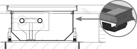
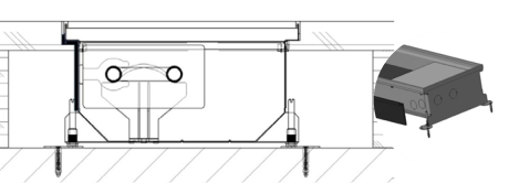
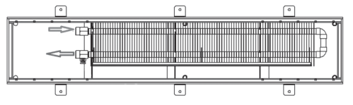
Select the correct convector position. Consult the convector position with an expert or your designer: if the convector is intended to be the main source of heat, it must be placed with the heat exchanger facing the room (PIC. 3), if the convector serves as an additional source of heat (as a thermal barrier), it is placed with the heat exchanger facing the window (PIC. 4).
| PIC. 3: Main source of heat | PIC. 4: Additional source of heat |
|---|---|
 |
 |
In case of a convector with a fan, always verify the regulation method of the convector. The method of regulation is stated on each technical sheet of the convector.
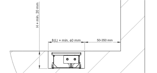
Installation Space
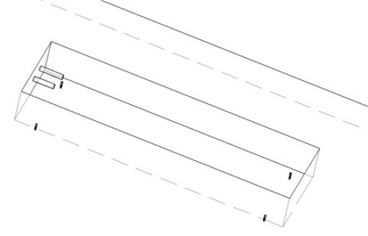
MINIB,a.s. recommends leaving sufficient space for convector installation in the structural opening. For installation in older floors, floors after renovation, or whenever sufficient space is not available, the dimensions of the installation opening should be equal to the convector height + at least 20 mm. The width and/or length (if only 1 convector is being installed) of the installation opening should correspond to the convector width (length) + at least 60 mm – see PIC. 5. Clearance around the convector should provide enough space for the water connection, electrical connections and for convector embedding in concrete. For new floors, MINIB, a.s. recommends at least +100 mm of free space around the convector; the height remains the same (H + at least 20 mm).
| PIC. 5 B – maximum width of convector body L – length of convector body H – height of convector body (without the adjusting legs) |
|---|
 |
Principles before installing the floor convector
MINIB floor convectors are designed for installation in solid or hollow floors where certain principles have to be applied.
Convectors, which are designed, for wet environment or for after-cooling are equipped with a Ø 18 x 23 mm drainage pipe. You will probably have to connect a hose leading to the sewer system, sump or another location.
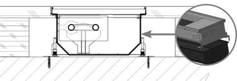
Principles of installation in HOLLOW floor
Use of reinforcement - U-channels When installing a convector in a hollow floor, in particular where more intensive traffic is expected (e.g., public buildings and office spaces) hollow floor U-channels must be used outside the convector body, which help ensure shape stability (PIC. 6).
| PIC. 6: Hollow floor – U-channel for floor convector |
|---|
 |
Use of thermal-insulations Use thermal insulation depending on the type and nature of the floor, especially when installed in parquet, floating or all-wood floors. Thermal insulation is to be applied on the outer surface of the metal body of the convector (PIC. 7). If the heat exchanger is located at one side of the convector, it is sufficient for the insulation to be applied only on the heat exchanger side. If the heat exchanger is placed symmetrically in the convector it is advisable to apply insulation on both sides. The insulation protects the finished floor from the direct heat of the convector. If you do not use this insulation there is a risk of quick drying out of the floor (parquet), leading to unstable joints between the wooden blocks. This risk is particularly high in hollow floors where the heat is also transmitted through the metal body of the convector to the floor cavity.
| PIC. 7: Hollow floor – thermal insulation for floor convector |
|---|
 |
Use of anti-vibration sheets For hollow floors MINIB,a.s. recommends to use anti-vibration sheets, to reduce the impact noise and/or any (fan) vibrations (PIC. 8). ::: alert warning::: For convectors with fan it is necessary to use anti-vibration sheet in hollow floors to dampen vibrations! :::
| PIC. 8: Hollow floor – anti-vibration sheets for floor convector |
|---|
 |
The standard convector is not equipped with U-channels, thermal insulation and anti-vibration sheets – must be specified before ordering).
The floor must be aligned as closely as possible with the convector perimeter. The expansion joint must be filled, for example with cork lining or silicone. This will prevent horizontal movement of the convector during load impact.
Height-adjustable anchoring is designed individually for hollow floors according to the required height and customer’s requirements.
Principles of installation in SOLID floor
Always make sure the convector is well embedded in concrete to prevent air bubbles under the convector bottom which could cause increased transmission of the impact noise and vibrations (from the fans).
For installation in solid floors it is not necessary to use U-channels. Consider the use of thermal insulation, especially for wooden floors.
INSTALLATION
A correctly installed convector is in horizontal position and the top edges of the trough are not damaged or bent in order to ensure correct functionality of the walk-on grille; has a standard frame aligned with the final floor.
It is recommended that the top convector cover (fiberboard) be left in place during concrete pouring to prevent the contamination of the convector interior.
Walking on this convector cover is not permitted!
In case of installation to the solid floor, before pouring concrete thoroughly seal (with adhesive tape) all holes (e.g., unused prepared attachment holes and installation braces) to prevent concrete from entering the convector trough. During the concrete pouring process, the convector must be fixed in the floor with anchoring screws to prevent vertical movement of the convector after cast in concrete or another suitable material. A vertical load may also be applied to the convector during the concrete pouring process.
Installation in the hollow floor is solved individually according to the type of floor.
Installation of convectors with and without fan with standard construction
- Insert 4 adjustment screws (6 screws for lengths over 2000 mm)
| PIC. 9 |
|---|
 |
- Place the convector in the structural opening, mark the holes for mounting the feet, and remove the convector.
| PIC. 10 |
|---|
 |
- Drill the marked holes (Ø 6 mm, depth 30-35 mm). Insert screw anchors in the holes.
| PIC. 11 |
|---|
 |
- Clear the perforated plugs of the holes for heating water connection.
| PIC. 12 |
|---|
 |
- If necessary, install U-channel reinforcements, thermal insulation or anti-vibration foils.
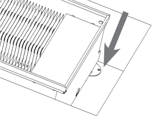
- Place the convector in the structural opening and install the heating water pipes.
| PIC. 13 |
|---|
 |
- Fix the convector using the attachment feet in the prepared screw anchors. Fix the feet using quick-hardening concrete.
| PIC. 14 |
|---|
 |
- If the convector is equipped with a drainage pipe connect it to the prepared drain.
| PIC. 15 Drainage pipe can be located on a side of the convector other than the side shown on the picture, depending on convector type. |
|---|
 |
- In case of a convector with a fan, install the power supply cable for the electronics in the placed convector. For safety reasons check whether the supply cable is live.
| PIC. 16 |
|---|
 |
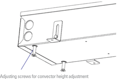
- Align the convector (with frame attached) using the adjustment bolts. Set the final height so that the convector frame is aligned with the inished floor.
| PIC. 17 |
|---|
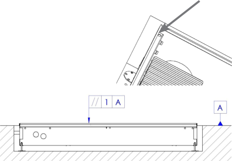 |
- Connect the inlet and outlet pipes. Perform final alignment according to PIC. 18.
| PIC. 18 |
|---|
 |
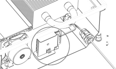
- In case of a convector with a fan connect the convector control unit using the connecting, control instructions, and follow the wiring diagrams in the instructions depending on the control type selected.
| PIC. 19 |
|---|
 |
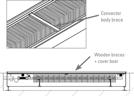
- Make sure that all openings inside the trough are sealed so that the convector interior is not contaminated during the concrete pouring process! Install struts of the convector trough and wooden braces together with fiberboard cover.
| PIC. 20 |
|---|
 |
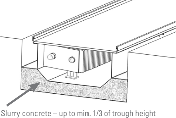
- Pour concrete slurry to at least 1/3 of the convector height in order to minimize the impact noise transmission. In the case of poor embedding of the bottom in concrete the convector with fan might resonate!
| PIC. 21 |
|---|
 |
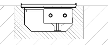
- The entire space around the convector must be subsequently filled with normal concrete up to the final height of the unfinished floor. The convector is now set in the unfinished floor, which is ready for floor finish installation (parquet, tiles, etc.)
| PIC. 22 |
|---|
 |
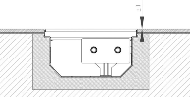
| PIC. 23 A correctly installed convector has a standard frame aligned with the floor finish. |
|---|
 |
Installation of convectors without a fan with universal construction
- Install adjusting screws - height adjustment by adjusting screws is done from inside the convector.
| PIC. 24 |
|---|
 |
- Select anchor leg position.
| PIC. 25: - Convector anchor leg position variants |
|---|
 |
- Place the anchor legs to the holes for attaching the legs to the convector. Screw the leg to the convector.
| PIC. 26 |
|---|
 |
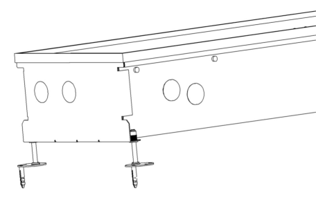
- To install the convector in the floor, follow the instructions from point 2 for the standard convector.If it is necessary to place the convector as close to the window as possible, it is allowed to not install the legs on the window side and fix the convector to the room side only.
Caution: If the anchor legs are inwards, first install the legs on the floor, after fixing them to the floor, attach the convector and screw them together.
- Changing the heat exchanger position and convector position: Take the heat exchanger, turn it and put it back on the beams in the convector.
| PIC. 27 | PIC. 28 |
|---|---|
 |
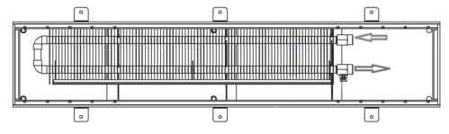 |
Illustration of the final installation of the convector
| PIC. 29 HOLLOW FLOOR | PIC. 30 SOLID FLOOR |
|---|---|
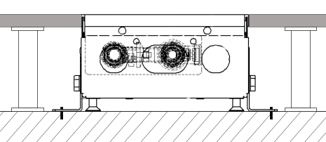 |
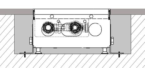 |
CONNECTION OF THE FITTINGS
The heating or cooling system is connected using the connection accessories. The type of fittings and hoses varies according to the type and purpose of the convector.
Before ordering it is always necessary to specify the method and position of connection, as well as the contents of the connection package and whether this package is part of the offer / order.
Connect individual inlet and outlet valves.
Water inlet: a ball or screw connection or a thermostatic valve is connected to the inlet. If thermostatic valves are used observe the flow direction of the valve and leave sufficient space for the valve with the given throughput. The angular screw fitting or angular thermostatic valve is connected to the inlet for connections from the window or room side.
Outlet (return pipe): The screw fi tting is always connected to the return pipe. In some cases, it may be necessary to switch the hot water inlet and outlet depending on the space required for thermostatic valve installation; however, fittings are always installed as described above.
Install sealing between each joint.
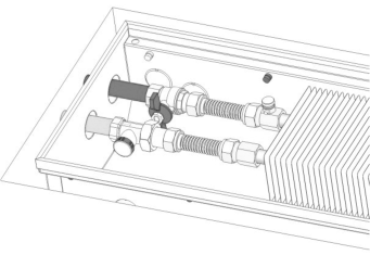
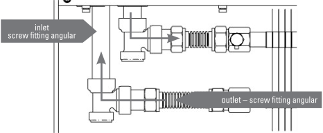
In case the water connection set includes flexi hoses, use the flexible stainless steel hoses (bellows hose) for connecting the heat exchanger. An example of direct and corner connection can be found on the picture 31, 32 and 33.
The stainless steel hoses are designed to withstand a maximum pressure of 1000 kPa. The hoses must not be stretched, subjected to tensile stress, or otherwise deformed.
| PIC. 31: Direct water connectiorn |
|---|
 |
| PIC. 32: Corner/side water connection – from the window side |
|---|
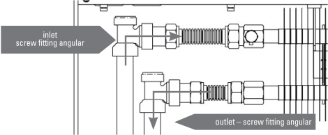 |
| PIC. 33: Corner/side water connection – on the room side |
|---|
 |
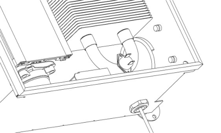
VENTING OF THE BODY
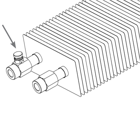
Vent (bleed) the unit using the air vent valve during the first use as necessary. In floor convectors, the air vent valve is located on the screw fitting of the heat exchanger.
| PIC. 34: Air vent valve |
|---|
 |