QUATTRO - User Manual
The QUATTRO controller is designed to control MINIB convector fans, which are equipped with DC motors (DC or EC) with a 4-wire connection (GND-PWR-TACHO-PWM). The controller is designed to be powered with direct current (DC) voltage from a switched source.
Basic functional properties of the controller:
- 24 V DC power supply,
- regulation of 1-circuit and 2-circuit convectors (heating, cooling, heating / cooling),
- 3 types of regulation (proportional, automatic, automatic with speed limitation)
- 2 × fan output,
- 3 × input for NTC or bimetallic temperature sensor,
- 2 × electrothermic valve head control supporting holding supply voltage,
- various types of electrothermic valve heads (NO / NC / without head)
- control voltage input in the range 0 - 10 VDC,
- input for switching the heating / cooling control regime 0 - 10 VDC,
- LED indication of controller status (2 × fan, 2 × temperature, 2 × ET head),
- basic settings using the button on the controller (SET).
Used symbols
| Symbol | Meaning |
|---|---|
| A/Ur (A) | Control signal from the superior system (thermostat, BMS,…). The voltage of this signal indicates to the controller the demand of the superior system for the power stage. The voltage ranges from 0 to 10 VDC. |
| COOL (C) | Control signal from the superior system (thermostat, BMS,…). The presence of the voltage of this signal indicates to the controller the request of the superior system for cooling regime. The voltage ranges from 0 to 10 VDC. |
| TS1 | Media temperature of the 1st circuit. |
| TS2 | Media temperature of the 2nd circuit. |
| TSA | Ambient temperature. |
| ET1-o/z | Electrothermic head of the 1st circuit: c ~ closed, o ~ open. |
| ET2-o/z | Electrothermic head of the 2nd circuit: c ~ closed, o ~ open. |
| FAN-speed | Fan speed step: 0-1-2-3 ~ off-low-medium-high. |
Connections
Power supply
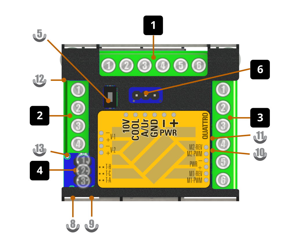
The controller is powered by 24 VDC. The supply voltage is applied to terminals 5️⃣(-): and 6️⃣(+) of connector 1.
Pay close attention to the correct polarity of the connection.
Control system
The control system issues requests for the behavior of the convector based on the user’s request and is typically not part of the heating unit. It can be implemented, for example, by a thermostat, BMS system, smart home system, potentiometer, etc.
The output of the control system is the control voltage and possibly the regime switching signal (heating/cooling).
The control system is connected to connector 1. All signals have a common reference at terminal 4️⃣(-). The control voltage signal (A/Ur) is fed to terminal 3️⃣, the regime selection signal (COOL) to terminal 2️⃣. A voltage of 10 VDC is available at terminal 1️⃣, which can serve as a reference voltage for switching with potential-free switches or as a thermostat supply.
Connector wiring overview 1
| Terminal | Signal | Direction | Area | Meaning |
|---|---|---|---|---|
| 1️⃣ | 10V | output | Control system | Output voltage 10 VDC |
| 2️⃣ | COOL | input | Control system | Heating/cooling regime switching |
| 3️⃣ | A | input | Control system | Fan speed control signal |
| 4️⃣ | - | reference | Control system | Reference (GND) for 10V/COOL/A signals |
| 5️⃣ | - | reference | Power supply | Negative pole of the power supply |
| 6️⃣ | + | input | Power supply | Positive pole of the power supply |
Fans
The fans are connected to connector 3. The power supply for both fans is connected to terminals 3️⃣(-) and 4️⃣(+). Speed control of fan 1 resp. 2 is connected to terminal 6️⃣ resp. 2️⃣. TACHO/REV signal from fan 1 resp. 2 is connected to terminal 5️⃣ resp. 1️⃣. Operating state of fan 1 resp. 2 is indicated by a green LED (10) resp. (11).
Connector wiring overview 3
| Terminal | Signal | Direction | Area | Meaning |
|---|---|---|---|---|
| 1️⃣ | M2-REV | input | Fan 2 | Fan 2 speed indication signal 2 (TACHO/REV) |
| 2️⃣ | M2-PWM | output | Fan 2 | Fan 2 speed control signal (PWM) |
| 3️⃣ | MP- | reference | Fan 1/2 | Negative pole of the power supply for both fans |
| 4️⃣ | MP+ | output | Fan 1/2 | Positive pole of the power supply for both fans |
| 5️⃣ | M1-REV | input | Fan 1 | Fan 1 speed indication signal (TACHO/REV) |
| 6️⃣ | M1-PWM | output | Fan 1 | Fan 1 speed control signal (PWM) |
Temperature sensors
Heating/cooling medium temperatures are measured by NTC or bimetallic sensors connected to the pair of terminals
1️⃣ (first circuit) a 2️⃣ (second circuit) of connector 4. The ambient temperature sensor is connected to the pair of terminals 3️⃣. The controller also allows operation without connected sensors.
The medium temperature of the first circuit is indicated by a red LED (8), the medium temperature of the second circuit is indicated by a blue LED (9).
Connector wiring overview 4
| Terminal (couple) | Signal | Direction | Area | Meaning |
|---|---|---|---|---|
| 1️⃣ | H | input | Temperature measurement | Temperature sensor of the first heating circuit (TS1) |
| 2️⃣ | C | input | Temperature measurement | Temperature sensor of the second heating circuit (TS2) |
| 3️⃣ | A | input | Temperature measurement | Ambient temperature sensor (TSA) |
Electrothermic valve heads
The electrothermic valve heads are connected to connector 2. The head for the first circuit is connected to terminals 1️⃣(-) and 2️⃣(+). The head for the second circuit is connected to terminals 3️⃣(-) and 4️⃣(+). The controller also allows operation without connected ET heads.
The supply status of the ET head of the first circuit is indicated by a red LED (12), the supply status of the ET head for the second circuit is indicated by a blue LED (13). The valve opening status then depends on the used head (NC/NO).
The voltage applied to the heads can be adjusted using configuration parameters CVP, CVL and CVH (service intervention).
Connector wiring overview 2
| Terminal | Signal | Direction | Area | Meaning |
|---|---|---|---|---|
| 1️⃣ | V-H- | reference | ET head 1st circuit | Reference voltage of the 1st circuit head |
| 2️⃣ | V-H+ | output | ET head 1st circuit | Power of the 1st circuit head |
| 3️⃣ | V-C- | reference | ET head 2nd circuit | Reference voltage of the 2nd circuit head |
| 4️⃣ | V-C+ | output | ET head 2nd circuit | Power of the 2nd circuit head |
Service connectors
Connector 6 is used for setting control parameters and access to service data of the controller. These connectors are intended only for use in the production of MINIB, or for use by a trained service technician.
Do not connect this connector in any way. Improper connection can permanently damage the controller.
The SET button (5) is used for limited user settings of the controller.
100## Regulation parameters
The following table provides a basic overview of the controller parameters.
| Parameter | Unit | Usually | Note |
|---|---|---|---|
| CRT | - | C | Type of regulation (‘A’,‘B’, ‘C’) |
| CRP | s | 900 | Fan speed switching period for regulations ‘B’ and ‘C’. |
| CAn | mV | Control signal voltage thresholds. Value n ∈ <0, 3> | |
| 1000 | - for opening valves (FAN-0, ET1-o resp. ET2-o); n = 0. | ||
| 2000 | - pro low speed (FAN-1); n = 1. | ||
| 5000 | - pro medium speed (FAN-2); n = 2. | ||
| 9500 | - pro high speed (FAN-3); n = 3. | ||
| CCH | mV | 5000 | COOL control signal voltage threshold. |
| ET1 | - | O | The 1st circuit valve head type (‘O’ - NO, ‘C’ - NC, ‘-’ - not connected) |
| ET2 | - | - | The 2nd circuit valve head type (‘O’ - NO, ‘C’ - NC, ‘-’ - not connected) |
| CVP | s | 180 | Valve full output power period (after that period the power is reduced to hold power). |
| CVL | % | 100 | Valve ‘hold’ power supply (percentage of supply voltage) applied after reaching full opening period. |
| CVH | % | 100 | Valve ‘full’ power supply (percentage of supply voltage) applied during the full opening period. |
| CWT | °C | 25 | Temperature threshold for heating medium. |
| CwT | °C | 20 | Temperature threshold for cooling medium. |
| CLI | - | off | Status status indication by LED diodes (off - indication off, on - indication on). |
Controller operation
Operation regime
The controller allows the selection of the operating regime (heating/cooling) by setting the voltage on the COOL input signal.
- If the voltage of this signal is below the level specified by the CCH control parameter (COOL < CCH), then the operating regime is set to heating.
- If the voltage reaches at least the level specified by the CCH control parameter (COOL ≥ CCH), then the operating regime is set to cooling.
The functioning of the controller in individual operating regimes depends on the type of used heat exchanger.
1-circuit heat exchanger (2-pipe)
For a convector with a 1-circuit heat exchanger, the behavior of the controller in both regimes is the same except for the medium temperature thresholds. The temperature sensor TS1 and the electrothermic head ET1 are used in both regimes.
- heating regime - sufficient medium temperature is determined according to the CWT control parameter (TS1 ≥ CWT).
- cooling regime - sufficient medium temperature is determined according to the CwT control parameter (TS1 < CwT).
In the case of a convector with a 1-circuit heat exchanger, only the head and the temperature sensor for the 1st circuit are connected.
2-circuit heat exchanger (4-pipe)
For the convector with a 2-circuit exchanger, the temperature sensor TS1 is used to measure the temperature of the heating medium, and the sensor TS2 is used to measure the temperature of the cooling medium. The controller controls the ET head for the heating medium (ET1) and the ET head for the cooling medium (ET2) separately.
- heating regime - sufficient medium temperature is determined according to the CWT control parameter (TS1 ≥ CWT); the ET2 head is permanently closed.
- cooling regime - sufficient medium temperature is determined according to the CwT control parameter (TS2 < CwT); the ET1 head is permanently closed.
In the case of a convector with a 2-circuit exchanger, the heads and temperature sensors for both circuits are connected.
Types of regulations
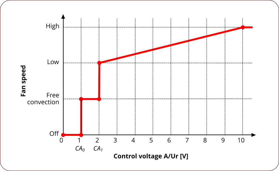
- Proportional (A) - fan speed is proportional to the control voltage.
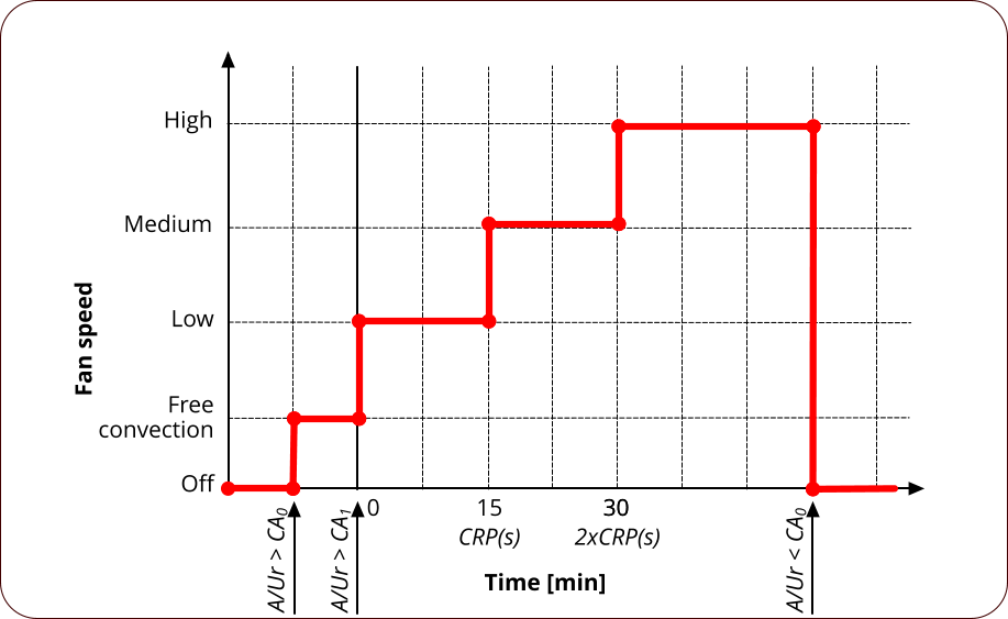
- Automatic (B) - fan speed increases in time in 3 steps: low-medium-high.
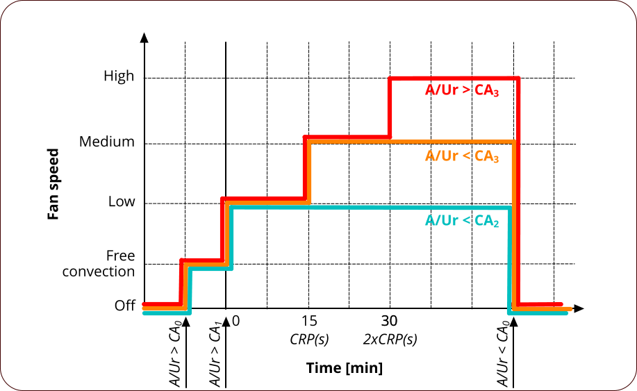
- Automatic with speed limitation (C) - the fan speed increases in time in 3 steps from low to the step given by the control signal (regulation B with maximum limitation).
Proportional (A)
The power of the convector with proportional control is proportional to the control voltage (A/Ur). The minimum and maximum power is determined by the controller configuration and is different for each convector model.
Automatic (B)
The convector power is controlled automatically regardless of the control voltage (A/Ur). The power is increased by one power level every CRP seconds from the moment the convector is started.
Automatic with speed limitation (C)
The control works similarly to the automatic control (B), but the magnitude of the control voltage is taken into account. The magnitude of the control voltage determines the highest power level that the control reaches.
Overview of A/B/C regulations states
| A/Ur | COOL | Medium temp | Proportional (A) | Automatic (B) | With limitation (C) | Note |
|---|---|---|---|---|---|---|
| < CA0 | * | * | FAN-0, ET1-z, (ET2-z) | FAN-0, ET1-z, (ET2-z) | FAN-0, ET1-z, (ET2-z) | |
| < CA1 | < CCH | insufficient | FAN-0, ET1-o, (ET2-z) | FAN-0, ET1-o, (ET2-z) | FAN-0, ET1-o, (ET2-z) | After the CVP time has elapsed, the valve supply is reduced to CV0% |
| ≥ CCH | insufficient | FAN-0, 2-p: ET1-o, 4-p: ET1-z / ET2-o |
FAN-0, 2-p: ET1-o, 4-p: ET1-z / ET2-o |
FAN-0, 2-p: ET1-o, 4-p: ET1-z / ET2-o |
After the CVP time has elapsed, the valve supply is reduced to CV0% | |
| < CCH | * | FAN-0, ET1-o, ET2-z | FAN-0, ET1-o, ET2-z | FAN-0, ET1-o, ET2-z | After the CVP time has elapsed, the valve supply is reduced to CV0% | |
| ≥ CCH | * | FAN-0, 2-p: ET1-o, 4-p: ET1-z / ET2-o |
FAN-0, 2-p: ET1-o, 4-p: ET1-z / ET2-o |
FAN-0, 2-p: ET1-o, 4-p: ET1-z / ET2-o |
After the CVP time has elapsed, the valve supply is reduced to CV0% | |
| < CA2 | < CCH | sufficient | FAN-prop ET1-o, (ET2-z) |
FAN-1-2-3 ET1-o, (ET2-z) |
FAN-1 ET1-o, (ET2-z) |
prop=proportional speed according to A/Ur between FAN-1 and FAN-3 Switching FAN-1-2-3 in the CRP interval. |
| ≥ CCH | sufficient | FAN-prop 2-p: ET1-o, 4-p: ET1-z / ET2-o |
FAN-1-2-3 2-p: ET1-o, 4-p: ET1-z / ET2-o |
FAN-1 2-p: ET1-o, 4-p: ET1-z / ET2-o |
prop=proportional speed according to A/Ur between FAN-1 and FAN-3 Switching FAN-1-2-3 in the CRP interval. |
|
| < CA3 | < CCH | sufficient | FAN-prop ET1-o, (ET2-z) |
FAN-1-2-3 ET1-o, (ET2-z) |
FAN-1-2 ET1-o, (ET2-z) |
prop=proportional speed according to A/Ur between FAN-1 and FAN-3 Switching FAN-1-2-3 in the CRP interval. |
| ≥ CCH | sufficient | FAN-prop 2-p: ET1-o, 4-p: ET1-z / ET2-o |
FAN-1-2-3 2-p: ET1-o, 4-p: ET1-z / ET2-o |
FAN-1-2 2-p: ET1-o, 4-p: ET1-z / ET2-o |
prop=proportional speed according to A/Ur between FAN-1 and FAN-3 Switching FAN-1-2-3 in the CRP interval. |
|
| ≥ CA3 | < CCH | sufficient | FAN-prop ET1-o, (ET2-z) |
FAN-1-2-3 ET1-o, (ET2-z) |
FAN-1-2-3 ET1-o, (ET2-z) |
prop=proportional speed according to A/Ur between FAN-1 and FAN-3 Switching FAN-1-2-3 in the CRP interval. |
| ≥ CCH | sufficient | FAN-prop 2-p: ET1-o, 4-p: ET1-z / ET2-o |
FAN-1-2-3 2-p: ET1-o, 4-p: ET1-z / ET2-o |
FAN-1-2-3 2-p: ET1-o, 4-p: ET1-z / ET2-o |
prop=proportional speed according to A/Ur between FAN-1 and FAN-3 Switching FAN-1-2-3 in the CRP interval. |
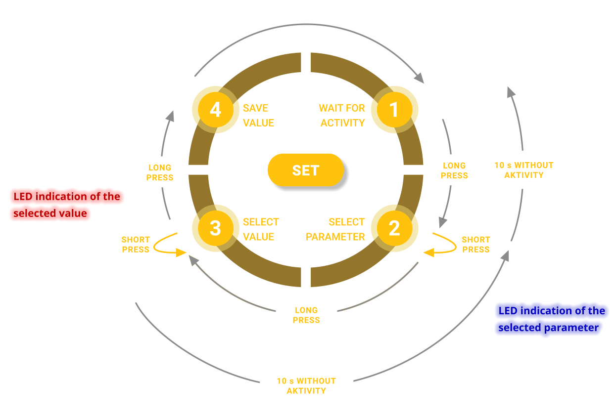
Configuration with the SET button
The controller allows limited user setting of the control type using the SET button. Detailed settings of all controller parameters can be performed via the service interface.
The setting with the SET button can be made at any time during the operation of the controller (with the supply voltage connected). The controller continues to control at the time of setting.
During setting are indication LEDs used to indicate the set parameters and do not indicate the control status.
Switching to the setting mode is performed by long pressing the SET button (longer than 0.5 s).
The set parameter is indicated by the flashing speed of the coolant temperature LED (9). You can go to the next parameter by briefly pressing the SET button. A long press of the button selects the parameter and proceeds to set the value of that parameter.
The parameter value is indicated by the flashing speed of the heating medium temperature LED (8). You can go to the next parameter value by briefly pressing the SET button. A long press of the button selects the value and sets it in the controller’s memory. Subsequently, the controller is restarted.
If the controller does not record activity (pressing the SET button) for 10 seconds, it leaves the setting mode without changing the parameter values.
| Parameter | Values | Description |
|---|---|---|
| 1. Type of regulation | 1. ‘A’ | Proportional (A). |
| 2. ‘B’ | Automatic (B). | |
| 3. ‘C’ | Automatic with speed limitation (C). | |
| 2. Status indication by LED diodes | 1. off | LED indication off. |
| 2. on | LED indication on. | |
| 3. Fan type | 1. D30 | Apply settings for the D30 fan. |
| 2. D50 | Apply settings for the D50 fan. | |
| 3. D65 | Apply settings for the D65 fan. | |
| 4. RESET | 1. nop | No operation. |
| 2. reset | Restart the control unit. |
Technical specifications
Power supply
| Parameter | Value | Note |
|---|---|---|
| Voltage | +7 – +28 VDC | In the case of voltage <11 V , the voltage value +10 V will not be observed at the thermostat output. |
| Power consumption | 20 mA | Power supply voltage 24 V, controller output inactive. In the case of active outputs (fan, valves, +10 V output), the power consumption is increased by the power consumption of the active outputs. |
Types of regulation
| Regulation | Parameter | Condition | Note |
|---|---|---|---|
| Proportional (A) | Function | Based on the control voltage (A/Ur), the fan speed changes linearly from FAN-1 to FAN-3. | |
| Dead band | A < CA0 | The controller does not respond. | |
| Heads activation | A ≥ CA0 | electrothermic heads are activated. | |
| Fans activation | A ≥ CA1 | The fan speed is set to the value determined by the control voltage: speed = FAN-1 + (A - CA1) × (FAN-3 - FAN-1) / (10 - CA1} speed ∈ <FAN-1, FAN-3> |
|
| Automatic (B) | Function | The fan speed increases over time in steps from FAN-1 to FAN-3. | |
| Dead band | A < CA0 | The controller does not respond. | |
| Heads activation | A ≥ CA0 | electrothermic heads are activated. | |
| Fans activation | A ≥ CA1 | The fan speed increases in steps from the time the activation condition (T0) is met with the CRP period: FAN-1 (T - T0 < CRP) FAN-2 (CRP ≤ T - T0 < 2 × CRP) FAN-3 (T - T0 ≥ 3 × CRP) |
|
| Automatic with speed limitation (C) | Function | The fan speed increases over time from FAN-1 to the stage given by the control voltage. | |
| Dead band A < CA0 | The controller does not respond. | ||
| ET head activation | A ≥ CA0 | electrothermic heads are activated. | |
| Fans activation | CA1 ≤ A < CA2 | The fan speed is FAN-1. | |
| CA2 ≤ A < CA3 | The fan speed increases in steps from the time the activation condition (T0) is met with the CRP period: FAN-1 (T - T0 < CRP) FAN-2 (T - T0 ≥ CRP) |
||
| A > CA3 | The fan speed increases in steps from the time the activation condition (T0) is met with the CRP period: FAN-1 (T - T0 < CRP) FAN-2 (CRP ≤ T - T0 < 2 × CRP) FAN-3 (T - T0 ≥ 3 × CRP) |
||
Supported thermostats (control systems)
| Thermostat | Output | Control type | Regulation | Note |
|---|---|---|---|---|
| Control voltage (A) | ||||
| Floating switch | defined by switch input | on / off | B | Mostly implemented relays. The controller does not share a common reference point (-/GND) with the thermostat. The input voltage for the switch can be provided by the controller (10 V). |
| 2-state control voltage | typically 0 / 10 V | on / off | B | The controller shares a reference point (-/GND) with the thermostat. The lower and upper thresholds can also be set to other voltage values. |
| Multi-state control voltage | i.e. 2/5/9 V | steps | A, B, C | The controller shares a reference point (-/GND) with the thermostat. The controller supports 3 + 1 steps (1 stage for head control). The control voltage thresholds can be set as desired. |
| Continuous control voltage | typically 0 - 10 V | linear | A, C | The controller shares a reference point (-/GND) with the thermostat. The control voltage thresholds can be set as desired. |
| Separate switches for control stages | usually 3 × 230VAC or 3 × 24VDC | steps | ❌ | Not supported, must be converted to control voltage by ADA converter or other means. |
| Regime selection (COOL) | ||||
| Without regime selection | - | - | H or C | The regime is permanently set to heating. If a permanent cooling regime is required, a jumper can be connected between the +10 V output and the COOL input. |
| Floating switch | defined by the switch input | on / off | H / C | Mostly implemented relays. The controller does not share a common reference point (-/GND) with the thermostat. The input voltage for the switch can be provided by the controller (10 V). |
| 2-state control voltage | typically 0 / 10 V | on / off | H / C | The controller shares a reference point (- / GND) with the thermostat. The switching threshold can be set to any voltage value. |
Heating/cooling circuits
| Type | Regime | Supported | Note |
|---|---|---|---|
| 1 circuit (2-pipe) | H | ✔️ | |
| C | ✔️ | ||
| 2 circuits (4-pipe) | H | ✔️ | |
| C | ✔️ |
Control of ET heads
| Parameter | Value | Note |
|---|---|---|
| Number of controlled heads | 2 | 1 × 1st circuit, 1 × 2nd circuit |
| Head operating voltage | the same as controller | It is possible to connect the head to a lower voltage than the operating voltage of the controller (by appropriate setting of parameters CVL and CVH in service settings). |
| Standard head position | NO, NC, no head | Possibility to configure in service settings (ET1, ET2). |
| Head power | up to 500 mA | |
| Setting the power supply level of the heads until they are fully open | ✔️ | The opening voltage level can be configured in the service settings. |
| Setting the power supply level of the heads after their full opening | ✔️ | The opening voltage level can be configured in the service settings. Note for controller 1.2.3: Doesn’t apply to ET2 which is allways supplied with 100 % of the power supply voltage. |
| Time setting until the head is fully open | ✔️ | Adjustable 0 s – 18 h in the service settings (CRP). |
| Operation without heads | ✔️ | The absence of a head can be set in the service settings. |
Heating/cooling medium temperature monitoring
| Parameter | Value | Note |
|---|---|---|
| Heating medium | ||
| Temperature threshold (minimum) | 1 - 110 °C | Adjustable by parameters in the service settings. |
| Hysteresis | -5/+0 °C. | Adjustable by parameters in the service settings. |
| Possibility to switch off measurement | ✔️ | Adjustable by parameters in the service settings. |
| Sensor presence monitoring | ✔️ | If the temperature sensor is missing, the temperature is always considered correct. |
| Cooling medium | ||
| Temperature threshold (maximum) | 0 - 99 °C | Adjustable by parameters in the service settings. |
| Hysteresis | -0/+5 °C. | Adjustable by parameters in the service settings. |
| Possibility to switch off measurement | ✔️ | Adjustable by parameters in the service settings. |
| Sensor presence monitoring | ✔️ | If the temperature sensor is missing, the temperature is always considered correct. |
Operating status indication
| Parameter | Indicator | Status | Appearance |
|---|---|---|---|
| Heating medium temperature | Red LED | insufficient | dim |
| sufficient | lit | ||
| metering off | 1 x flash / 2 s | ||
| sensor disconnected | 10 x flash / 1 s | ||
| Cooling medium temperature | Blue LED | insufficient | dim |
| sufficient | lit | ||
| metering off | 1 x flash / 2 s | ||
| sensor disconnected | 10 x flash / 1 s | ||
| ET head of the 1st circuit | Red LED | without power | dim |
| full power | lit | ||
| maintenance power | 1 x flash / 1 s (flash length corresponds to % limit) | ||
| ET head of the 2nd circuit | Blue LED | without power | dim |
| full power | lit | ||
| maintenance power | 1 x flash / 1 s (flash length corresponds to % limit) | ||
| Fan output power | Green LED | without power | dim |
| regulating to the required speed | flashes 0.5 s / 0.5 s | ||
| regulated | lit | ||
| fan disconnected | flashes 0.1 s / 5 s |
Contacts
MINIB, a.s.
Brunclíkova 1875/17, 162 00 PRAHA 6, Česká republika
+420 604 767 677
minib@minib.cz
WWW
Servce Bohemia/Slovakia
Stanislav Trávníček
+420 603 964 013
travnicek.stanislav@centrum.cz
Service Moravia
Rostislav Španko
+420 608 888 860
tvpservis@tvpservis.cz
Customer service (questions / orders / complaints)